Cooled Canon 450D AstroCamera

The purpose of this project was to take a standard Canon 450D DSLR camera and actively cool the CCD sensor. The reason for cooling the sensor is to reduce the cumulative effect of thermal noise generated when performing the long exposures required for Astro Photography. The objective was to cool the sensor by at least 15C below ambient and be able to maintain this temperature using a thermostat. The cooling was to introduce no electronic ill effects and result in no condensation and/or freezing of the CCD or other components. Further, vibration was to be kept to a minimum resulting in no observable adverse effect to image quality.
Copyright ® 2011 by Dave Trewren À All Rights reserved À E-Mail: dtrewren@ipwireless.com

Preventing the build up of dew and subsequent freezing has been by far the most problematic aspect of this project. Dew forms when an object is cooled to below the dew point. Below this temperature dew forms as water vapour condenses on the cold object, subsequently below or about zero degrees the condensation freezes to form frost and ice.
The dew point is give by the following approximation :
Td = Ta - [(100 - Rh) / 5]
Where :
Td - dew point temperature
Ta - ambient temperature
Rh - relative humidity %
So it can be seen that lowering the relative humidity lowers the dew point with respect to ambient. In the limit at 100% Rh (Td = Ta) and water vapour spontaneously condenses at ambient.
In order mitigate the effect of condensation we can either lower relative humidity or warm the object in question. In this project both approaches have been employed to prevent dew/frost from forming on or around the camera CCD sensor.

Excellent instructions detailing how to dissemble the Canon 450D have been provided by Gary Honis at the following location :
www.ghonis2.ho8.com/rebelmod450d1.html
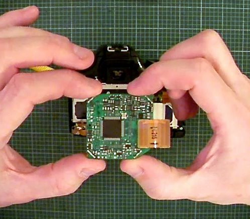
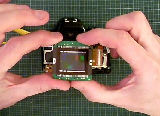
I do not intend to reiterate GaryÆs excellent explanation as it is complete. I have added here a few images of my camera after the strip.
www.ghonis2.ho8.com/rebelmod450d1.html
I do not intend to reiterate GaryÆs excellent explanation as it is complete. I have added here a few images of my camera after the strip.
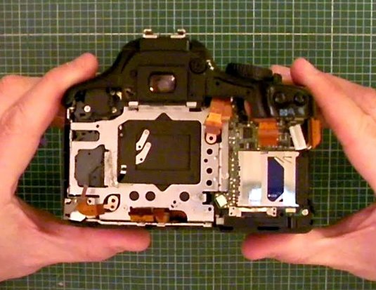
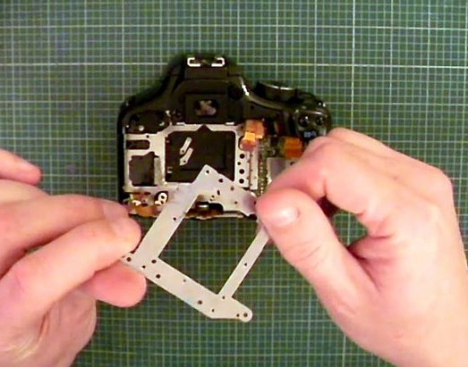

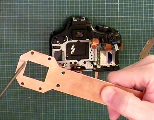
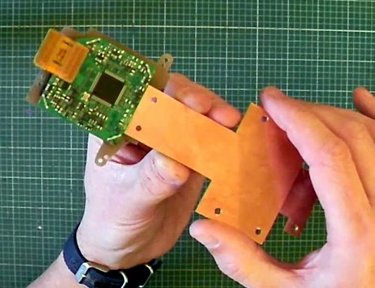
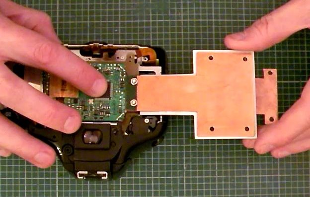
The original Canon CCD mounting plate is made from metal. As the CCD sensor cools the mounting plate will also cool and condensation would then probably form on the plate inside the camera. To prevent this from occurring I re-fabricated the mounting plate from fibreglass single sided PCB board. This board is strong and easy to work. The copper is also acts as a thermal conductor on the hot finger side.

- Active CCD cooling using a cold finger
- Active filter and filter housing heating using hot finger
- Sealed low humidity filter chamber
- Baader IR cut filter
- Thermostat control of temperature
- LCD temperature readout
- Low vibration fan assisted cooling
- Built in camera power source
- External access to camera USB connection
- Active filter and filter housing heating using hot finger
- Sealed low humidity filter chamber
- Baader IR cut filter
- Thermostat control of temperature
- LCD temperature readout
- Low vibration fan assisted cooling
- Built in camera power source
- External access to camera USB connection
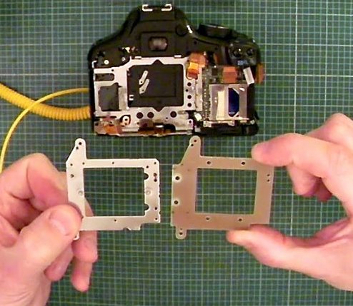
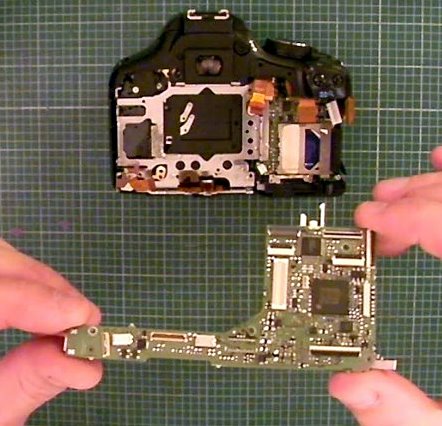
This image shows the original mounting plate on the left and my re-fabricated plate on the right.
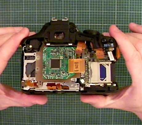
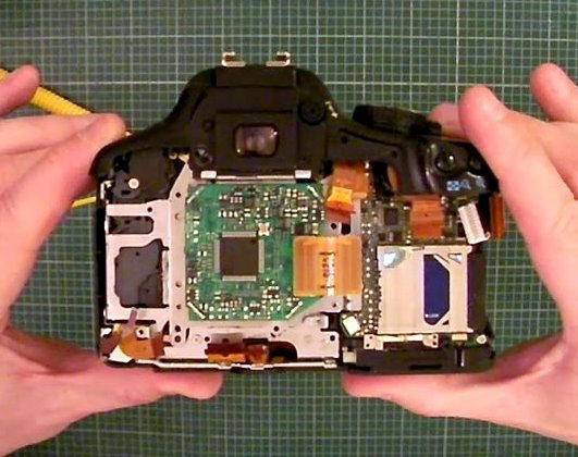
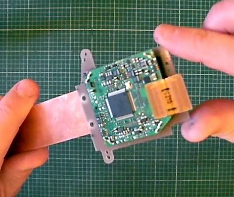
This image shows CCD sensor mounted on the new mounting plate and inserted into the camera body,

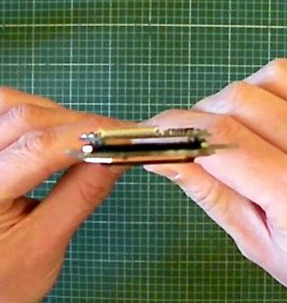
The cold finger is fabricated from 18swg (1.2mm) copper sheet. The CCD sensor is surface mounted to a circuit board. There is a small gap between the CCD sensor and this circuit board. The cold finger is inserted in said small gap with a piece of electrical insulation on the circuit board side. The circuit board is double sided, the insulation prevents the copper finger from shorting out the board. Thermally conductive grease is used on the sensor side of the copper to provide a good thermal connection. The opposite end (from the CCD) of the copper finger widens out to locate over the Peltier element.
The cold finger fabrication
Inserting the cold finger into the gap between CCD and circuit board

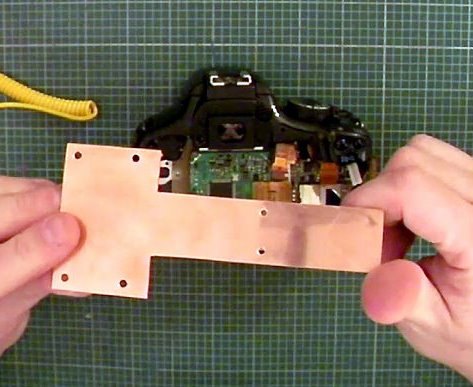
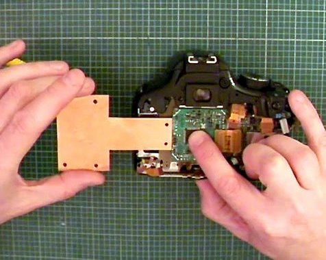
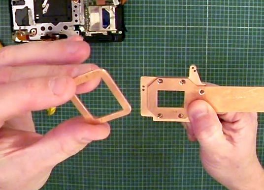
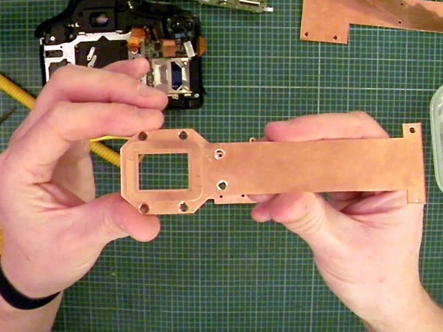
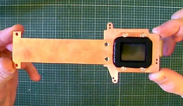
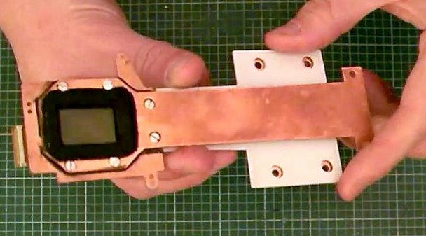
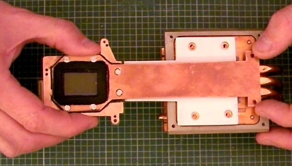
The hot finger is also fabricated from 18swg (1.2mm) copper sheet. The hot finger screws to the air side of the fibreglass mounting plate. A second small copper ring housing is then attached to the hot finger. As can be seen in the images the copper ring housing aperture is slightly larger than that of the hot finger, this creates a recess and allows the Baader IR cut filter to be mounted with a small clearance all around. The opposite end (from the CCD) of the copper widens out to pass over the cold finger and locate to the hot side of the Peltier element. Thus heat is transferred to the filter and housing preventing the assembly from dewing up and freezing.
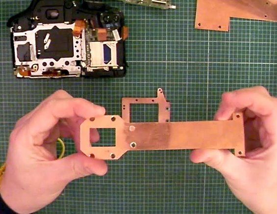
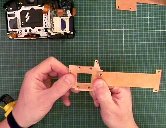
The hot finger fabrication
The hot finger fabrication & mounting plate
The hot finger fabrication, mounting plate & filter housing ring

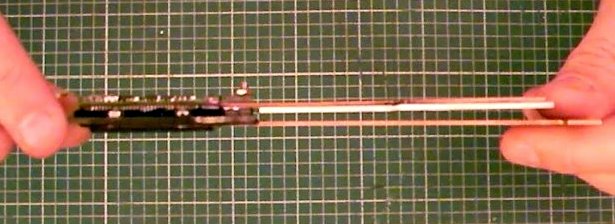
Note the small capillary channel cut into the hot finger reverse side. When the entire hot/cold finger, CCD sensor is assembled and sealed this channel connects the inner void between the sensor and Baader filter to the outside air.
The entire assembly was then placed in a low humidity environmental chamber before the capillary was sealed off. The Rh acheived in the sealed chamber was approximately 9%.
The entire assembly was then placed in a low humidity environmental chamber before the capillary was sealed off. The Rh acheived in the sealed chamber was approximately 9%.
The CCD sensor is mounted into the new mounting plate. The hot finger is then attached together with the Baader filter and mounting ring. This assembly is then sealed (not the capillary). The cold finger is inserted and screwed into place using a small fibreglass mounting bracket. A polycarbonate insulating sheet is inserted in between the hot & cold fingers to act as a thermal barrier and form one side of the enclosure for the cold finger.
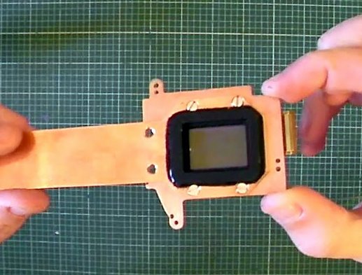
Assembled hot finger & CCD rear
Assembled hot finger & CCD air side
Assembled hot finger & CCD air side
Gap for cold finger insertion
Cold, hot finger spacing and polycarbonate
Cold, hot finger & CCD sensor inserted into camera
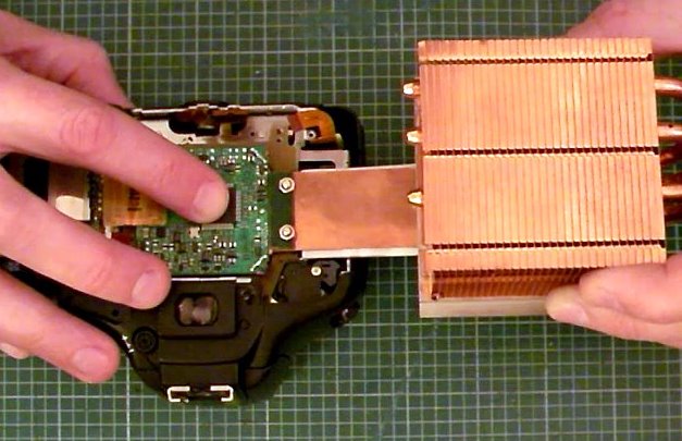
Cold, hot finger & CCD mounted on heatsink
Cold, hot finger & CCD mounted on heatsink and inserted into camera

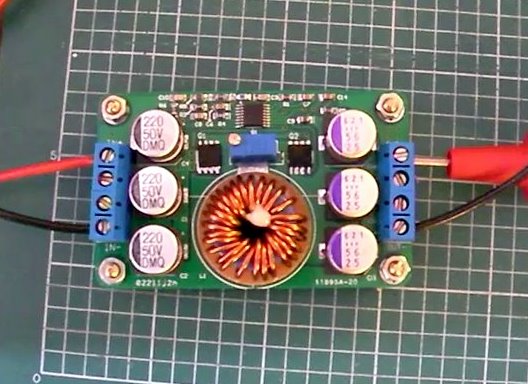
Following initial assembly the design was bench tested to flush out any issues. Initial testing was very promising, the sensor cooling well, no condensation and no electrical/electronic problems. The Peltier is rated at 136W but I am only operating it at around 50W. In order to drive the Peltier I used a small high efficiency switch mode power supply module which after a small modification to reduce the switch on voltage drives the Peltier at a constant current of 5A. The camera power is supplied by a very small second switch mode supply module.
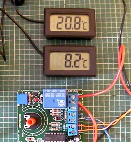
The thermostat is very crude and is simply a voltage reference and comparator - it works surprisingly well. The hysteresis is around two degrees but this is almost entirely due to the time heat takes to travel along the cold finger to the CCD sensor and temperature sensor. I plan to replace the thermostat with a PIC microprocessor and implement a PID controller to control the temperature more accurately.
The thermostat is very crude and is simply a voltage reference and comparator - it works surprisingly well. The hysteresis is around two degrees but this is almost entirely due to the time heat takes to travel along the cold finger to the CCD sensor and temperature sensor. I plan to replace the thermostat with a PIC microprocessor and implement a PID controller to control the temperature more accurately.
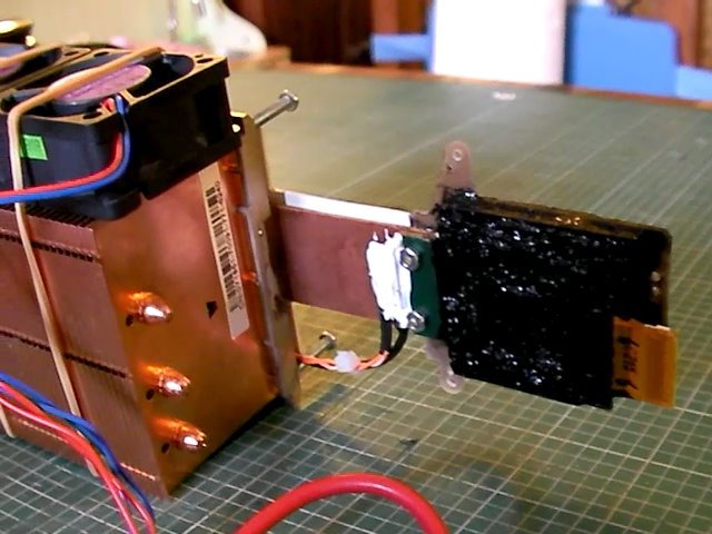
Everying assembled and lashed together
CCD circuit board potted in sealent. Temperature sensors visable mounted using thermal epoxy
High efficiency switch mode power supply
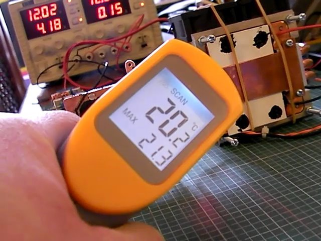
Ambient, CCD temperature & thermostat
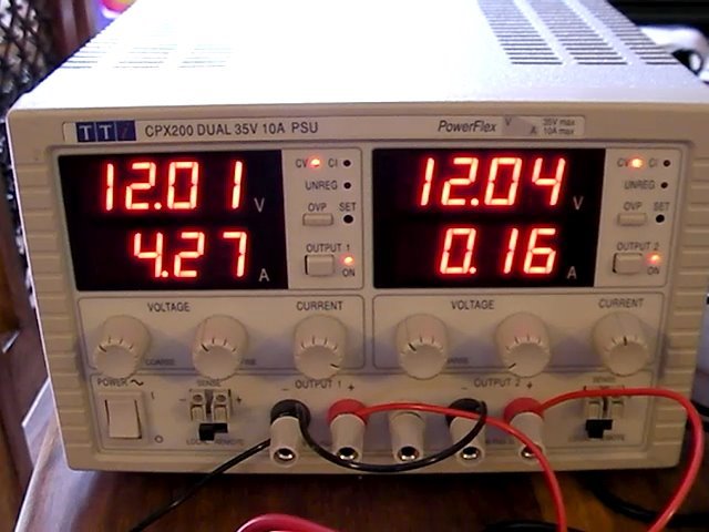
Peltier current
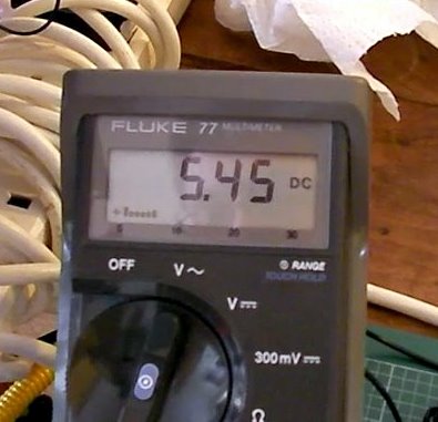
Switch mode primary supply voltage/current on left hand side readout
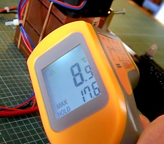
Hot finger temperature
Cold finger temperature
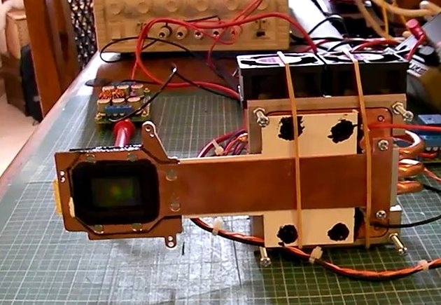
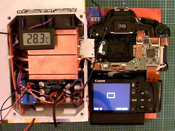
Almost complete working unit, just a bit of mechanical stuff to complete (not cooling in shot)
Dave Trewren 27/3/2011
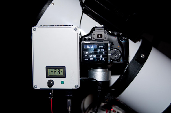
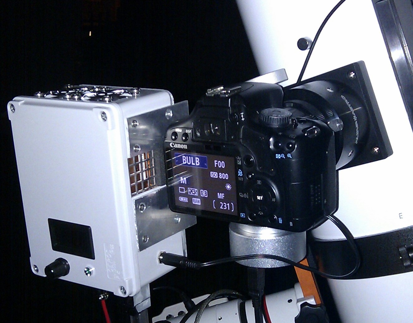
These images show the final cooled 450D attached to my Altair Astro f/4 8' imaging Newtonian. The camera is powered from the cooling box. The rotary control is temperature setpoint and the LED indicates the thermostat state. The TS 9mm OAG and Starshoot autoguider can also be seen.
The modified 450D weighs in at 1.47Kg including the OAG & Starshoot autoguider
The modified 450D weighs in at 1.47Kg including the OAG & Starshoot autoguider