


SharpSky V2 - telescope focuser (PCB based)

The objective of the SharpSky focuser project was to design and build an ASCOM compliant low cost absolute focuser with a manual scope side control option. The design should be simple in construction and lightweight. The original design was based around an off the shelf PIC microprocessor development card. This original design is the subject of the following website :
www.dt-space.co.uk/SharpSky
Having received quite a bit of interest in the design coupled with an increase in the development card cost I decided to design and have fabricated a dedicated PCB board. The PCB version of the design reduces cost, simplifies construction and is more compact.
www.dt-space.co.uk/SharpSky
Having received quite a bit of interest in the design coupled with an increase in the development card cost I decided to design and have fabricated a dedicated PCB board. The PCB version of the design reduces cost, simplifies construction and is more compact.

Dave Trewren 20/3/2012
- Low cost
- Simple construction based around an
off the shelf PIC micro
- Bootloader for simple firmware upgrade
- ASCOM compliant
- Absolute positioning
- USB connectivity
- Manual scope side focus control
- Variable manual rate
- Stepper motor mechanical drive
- Beam coupler to minimise shaft alignment issues
Copyright © 2011 by Dave Trewren · All Rights reserved · E-Mail: dtrewren@ipwireless.com

I have put together a kit of parts which, once built, will provide a complete focuser as shown in the videos. I think it should be possible to build the kit relatively easily over the course of a few hours. The only component not supplied is the bracket for mounting the motor housing onto the telescope. As you can appreciate it would be very difficult to supply a range of brackets for all the different scopes out there and therefore I leave that to the end user. Generally a short length of aluminium sheet is all that is needed to mount the motor housing.
Here is a list of parts included in the SharpSky kit :
- Dedicated PCB board (double sided, through hole plated)
- Main controller enclosure (marked but not drilled)
- Manual controller enclosure
- Motor enclosure
- Manual control knob
- Manual control cable
- Manual control plug (4 pin mini DIN)
- Temperature probe plug (3 pin mini DIN)
- Motor lead (9-way male to 9-way female D-type)
- Stepper motor (12v 2 phase unipolar) -> 2048 steps/rev
- Shaft beam coupler (drilled, tapped & fitted with 3mm grub screws)
- Quality turned pin IC sockets
- All required fastenings
- PIC18F2550 (inc firmware & bootloader)
- ULN2003A Darlington driver
- Rotary encoder (manual control)
- Digital temperature probe
- 4MHz crystal
- All capacitors, resistors & diode
- Five LED’s and housings
- All PCB mounted connectors

The following video show the SharpSky unpopulated & populated PCB, the motor housing, manual controller and motor interconnection.


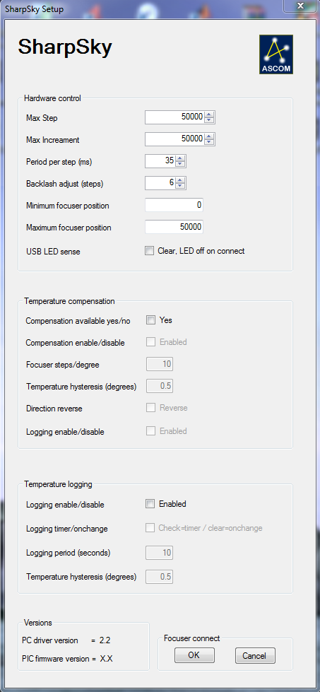
Hardware control
Max Step
largest step count permitted
Max Increament
largest single step increament permitted
Period per step (ms)
The period in ms for each stepper motor step. Influences the motor speed and torque produced
Backlash adjust (steps)
The number of steps automatically introduced on motor direction change to compensate for machanical backlash
Minimum focuser position
The focuser will stop at this point when decreasing in position
Maximum focuser position
The focuser will stop at this point when increasing in position
USB LED sense
Changes the sense of the USB status LED when connected/disconnected
NOTE 1 : The aspect ratio of the driver window has been changed to better fit a typical laptop screen resolution
NOTE 2 : The temperature compensation & logging onchange period is once every ten seconds
SharpSky PC ASCOM driver : SharpSky_ASCOM_Driver
NOTE 2 : The temperature compensation & logging onchange period is once every ten seconds
SharpSky PC ASCOM driver : SharpSky_ASCOM_Driver
Temperature compensation
Compensation available yes/no
Informs the client of feature availability
Compensation enable/disable
Enables/disables compensation within the driver
Focuser steps/degree
Amount focuser will move per degree or fraction of degree
Temperature hysteresis (degrees)
Amount by which temperature must change to invoke a move
Direction reverse
Reverses the direction of compensation, ie focuser tube in or out
Logging enable/disable
Enables logging of information to file (see below for detail)
Temperature Logging
Logging enable/disable
Enables/disables function
Logging timer/onchange
Checked, logging at logging period (below). Clear logging when temperature hysteresis exceeded
Logging period (seconds)
Period after when I log is made assuming enabled
Temperature hysteresis (degrees)
Temperature change required to trigger log if enabled
Versions
Respective driver and PIC firmware versions. PIC version obtained from PIC device on request
Focuser connect
Connect/disconnect from SharpSky hardware
Respective driver and PIC firmware versions. PIC version obtained from PIC device on request
Focuser connect
Connect/disconnect from SharpSky hardware
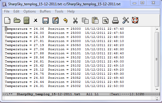
The following shows and example of a temperature log file. The first example shows logging in timer mode and the second logging in on-change mode. Log files are generate on the C:\ drive and have the following format : SharpSky_templog_dd-mm-yyyy.txt. Therefore a new log file will be generated for each imaging night.
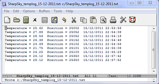
On change logging with a hysteresis of 0.5C - again applying a finger and moving the focuser about
I simply put my finger on the sensor for a while and then removed while moving the focuser about
The following video shows the focuser in manual operation mode without a connection to the PC. Manual mode and PC control operate together or independently.
The following video shows the focuser operating via the PC USB connection.
The following shows the layout and operation of the ASCOM compliant driver. Via the driver the motor hardware, temperature compensation and logging can be controlled.

The following shows the layout and operation of the PC based bootloader application. This application together with the PIC based bootloader allows the PIC to be reflashed via the USB connection without requiring dedicated PIC programming hardware.
In order to get the SharpSky controller into boot mode depress and hold the manual control button and then apply power. The manual control LED will rapid flash indicating the PIC is in boot mode and the PC application will respond with the message 'SharpSky PIC attached'. The PC application buttons will also enable on connection.
The very first connection to the PC or new USB port may take a few seconds longer to enter boot mode while the PC detects SharpSky as a new HID device.
SharpSky bootloader PC application : SharpSky_BootLoader
Right click on link below and select 'Save link as ...'
SharpSky firmware image : SharpSky_HEX
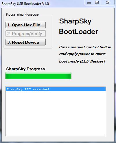
1. Open Hex File
User browses for the new the HEX file firmware image.
2. Program/Verify
Instruct the PC bootloader application to erase the current application, reflash the PIC and perform verification.
3. Reset Device
One reflashed, reset the PIC device resulting in the execution of the new firmware.
User browses for the new the HEX file firmware image.
2. Program/Verify
Instruct the PC bootloader application to erase the current application, reflash the PIC and perform verification.
3. Reset Device
One reflashed, reset the PIC device resulting in the execution of the new firmware.

In order to help with the kit build I have produced a document in PDF format. This document details the steps involved in building a SharpSky focuser. I am sure the document will not be everything you need to know so I really value feedback such that the instructions can be improved on. It’s always tricky writing a construction document for your own design as there is a tendency to take things for granted and leave holes that need filling.
At this stage I have to address the vulgar subject of kit pricing. I have tried to make the kit as cheap as possible sourcing many parts from China, including the PCB. For the initial run of kits I have factored in a small amount for the time required to put kits together but not much.
The following are the numbers I have come up with :
- Complete kits of parts Ł68 inclusive of UK delivery
- Controller box only Ł50 inclusive of UK delivery
I am not running this project as a business hence the low cost. The original idea was to design and build something useful and affordable which could be scaled for multiple telescopes.
Link to the construction document : SharpSky_build.pdf
Copyright © 2011 by Dave Trewren · All Rights reserved · E-Mail: dtrewren@ipwireless.com